Introduction
This manual is devoted to the development of ARGoS modules. Adding new modules is easy, although some parts of the ARGoS internals might be tricky to understand at first.
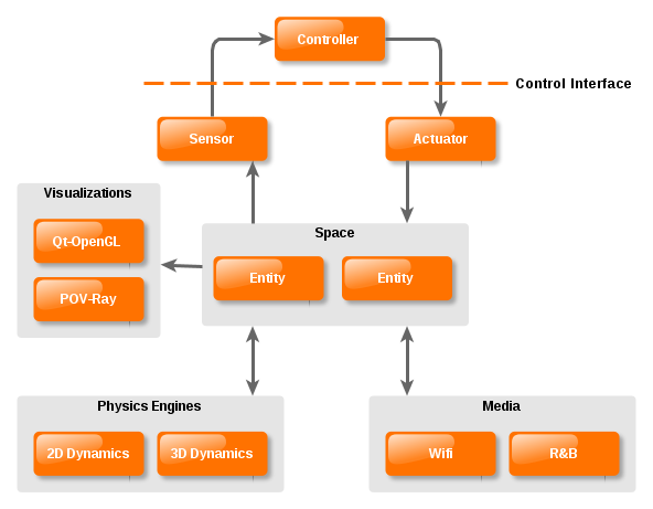
The general architecture of ARGoS is reported here:
Each box in the picture indicates a module which, in practice, corresponds to a class definition (e.g., a sensor) or to a collection of classes (e.g., a physics engine). You can add any kind of implementation.
Setting Up Your Development Environment
The ARGOS_PLUGIN_PATH Environment Variable
Even though the standard modules are shipped directly with ARGoS, this does not mean that you need to patch the ARGoS sources to add new modules. ARGoS is designed to look for user modules in any directory you list in the ARGOS_PLUGIN_PATH environment variable. For instance, if your development folder is ~/myargosstuff and the binaries are all located in ~/myargosstuff/build, you can set
$ export ARGOS_PLUGIN_PATH=$HOME/myargosstuff/build
and ARGoS will look for dynamic libraries in that directory. On Linux, ARGoS will look for .so files; on Mac, it will look for both .dylib and .so files. ARGoS does not recursively descend into the directories you specify in ARGOS_PLUGIN_PATH. If you scattered your binaries across multiple directories, e.g., ~/myargosstuff/build/module1 and ~/myargosstuff/build/module2, you can tell ARGoS to visit them as follows:
$ export ARGOS_PLUGIN_PATH=$HOME/myargosstuff/build/module1:$HOME/myargosstuff/build/module2
You can specify both absolute and relative paths in ARGOS_PLUGIN_PATH, and ARGoS will deal with them correctly.
You might want to add your export ARGOS_PLUGIN_PATH=… command to ~/.bashrc to avoid having to retype it every time you open a new console.
Directory Structure
In theory, you’re not supposed to respect any specific directory structure for your code. You can lay out the files as you like, and then set ARGOS_PLUGIN_PATH to tell ARGoS where to look for libraries.
However, if you intend to redistribute your code and install it along with the standard plugins of ARGoS, you should respect the conventional directory structure of ARGoS:
argos3/
+- core/                           # ARGoS core files
+- plugins/                        # Plugins files
   +- robots/                      # Robot files
      +- generic/                  # Generic robot devices
         +- control_interface/     # Control interface for generic robot devices
         +- simulator/             # Simulation logic for generic robot devices
      +- e-puck                    # e-puck files
         +- control_interface/     # e-puck specific control interface
         +- simulator/             # e-puck simulation logic
      ...                          # More robots...
   +- simulator/                   # Simulator-only files
      +- entities/                 # Entities that compose a robot
      +- media/                    # Simulated communication media
      +- physics_engines/          # Physics engine files
         +- dynamics2d/            # Dynamics 2D engine files
         +- pointmass3d/           # Pointmass 3D engine files
      +- visualizations/           # Visualization files
         +- qt-opengl/             # Qt-OpenGL visualization files
For instance, if you want to add a new robot and redistribute it, you will need to create this directory structure:
myargosstuff/
+- argos3
   +- plugins/
      +- robots/
         +- my_robot/
            +- control_interface/
            +- simulator/
Make sure to install your header files in $prefix/include/ respecting this directory structure. Libraries go directly in $prefix/lib/argos3 without the above structure. To know what $prefix is on your computer, type
$ prefix=$(dirname $(which argos3)); echo ${prefix%bin}
Compilation Script Configuration
In principle, you can use any way to configure the compilation of your files. The ARGoS examples, however, already offer a nice starting point based on CMake that shows how to detect ARGoS and compile against it. It is a good idea to start from those scripts, or from those shipped with the ARGoS sources.
ARGoS Simulated Objects 101
To be able to simulate an object, ARGoS needs to do the following things:
-
Store its state, by representing the robot as a collection of entities (see below).
-
Read and update its state. Actuators, physics engines, and media change the state of a robot; sensors read it. Sensors and actuators are directly available to the controller to interact with the simulated world. Physics engines and media remain hidden to the controller.
-
Visualize its state. This is obtained through a visualization model, such as an OpenGL one. State visualization is optional in ARGoS.
In ARGoS, a simulated object is a collection of class definitions. Each class takes care of a certain aspect of the simulation—storing state, changing it, visualizing it.
Entities: Representing the State of a Simulated Object
Any simulated object in ARGoS is composed of entities. Simple simulated objects, such as lights, might be just a single entity; complex objects, such as robots, are structured as trees of entities. An entity contains the state of a simulated object, such as its position/orientation in the world and the configuration of its devices (sensors/actuators).
The basic entity class in ARGoS is CEntity; every other entity inherits from it. This class introduces the most fundamental methods, such as GetId() to get the string identifier of an entity, GetParent() to get the parent of an entity, and Init(), Reset() and Destroy() to handle the entity lifetime. Entities can be enabled or disabled. When an entity is enabled, ARGoS calls its Update() method at every simulation step; when it is disabled, that method is not called. Disabling entities is a way to save computational resources when the information stored by a certain entity is not relevant for an experiment.
To compose entities, ARGoS offers the CComposableEntity class. Any complex simulated object must inherit from it. This class introduces methods to manage multiple components (add, get, update, etc.).
If you want your simulated object to interact physically with other objects, which is usually the case, you must use an embodied entity (CEmbodiedEntity). This type of entity stores information such as the current position and orientation of the entity in the world and its anchors (see below). The embodied entity is the link between a robot and its model in the physics engine. One of the most innovative aspects of ARGoS is that one can use multiple physics engines in parallel during a simulation. The embodied entity is designed to manage automatically which physics engine is currently in charge of the associated robot. In this way, other sensor which need to know the position/orientation of the body of an object do not need to interface with the physics engines directly.
Some objects can be associated to a controller defined by the user. Robots are the primary example of this kind of simulated object. The controllable entity (CControllableEntity) stores a reference to the controller associated to a robot, and manages the sense/control step/act cycle of a robot.
Any robot, at its essence, is a composable entity with two children: an embodied entity and a controllable entity. Any other entity depends on the specific type of robot (wheeled, flying, etc.). The UML class diagram below summarizes what explained so far.

Reading and Changing State
To understand how state is stored, read, and changed, look at this picture:
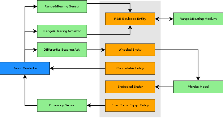
This picture shows how a robot equipped with wheels, a proximity sensor, and a communication device (range-and-bearing) is composed. Each entity stores an aspect of the robot related to its devices and capabilities. Each entity is associated with a specific module that either reads the entity status, or writes it.
-
The proximity sensor takes the current position of the sensors from the proximity sensor equipped entity and calculates the new readings. The readings, in turn, are given to the controller.
-
The current speed of the wheels is stored in the wheeled entity. The speed is changed by the differential steering actuator, which is used in the controller. The wheel speed is read by the physics model to update the robot position in the physics engine.
-
The embodied entity, as explained above, is updated by the physics model.
-
Communication is typically composed of a sensor (to receive messages) and an actuator (to send messages). In this example, the range-and-bearing actuator stores the message to broadcast in the range-and-bearing equipped entity. This message is then collected by the range-and-bearing medium, which calculates which robots receive which messages. The list of messages received by a robot is then linked in the range-and-bearing entity, and it in turn read by the range-and-bearing sensor. The robot controller uses the latter to collect the received messages.
As this example shows, entities act as a mediator among different types of modules. Entities do not contain the logic associated with an aspect of a robot; rather, they contain status information that is used by the other modules to do their job.
Visualizing a Robot
Visualizing a robot can occur in different ways. A GUI might want to draw an object in either 2D or 3D. It is also possible to define text-only visualizations tailored for later analysis, e.g., of the object trajectories. ARGoS can be also run without outputting anything at all.
Visualizations "own" the management of the simulation loop. This is done to allow developers to wrap ARGoS within any GUI system, such as Qt or SDL. "Owning" the simulation loop means that it is the visualization that calls the methods CSimulator::Init(), CSimulator::Reset(), CSimulator::UpdateSpace(), and CSimulator::Destroy().
The visualization is free to draw the state of the simulation at any time between the calls of the methods of the simulation loop. It is up to a simulation to perform the mapping between a robot and its actual appearance (e.g., a 3D model).
In the default visualization provided by ARGoS, Qt-OpenGL, each robot is associated to a model. When it’s time to draw a robot, the model is given the robot entity. The model then reads the status of each of the relevant entities that compose the robot and draws them. For instance, if the robot has LEDs, the model reads the state of the LED-equipped entity and draws the LEDs lit up in the right colors. A class diagram of how the Qt-OpenGL visualization is structured is reported below.
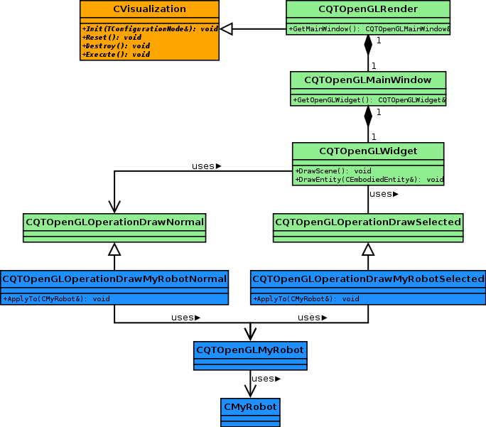
CQTOpenGLRender implements the basic Qt mechanisms (e.g., creates a new QApplication) to create the GUI. The main window is CQTOpenGLMainWindow, which in turn contains the widget in which the robots are drawn: CQTOpenGLWidget. Whenever this widget needs to be redrawn, the method DrawScene() is called, which in turn calls DrawEntity() for every object to draw. This method calls CQTOpenGLOperationDrawMyRobotNormal::ApplyTo() (the details of how this method gets called are explained later). Finally, the latter calls any method of CQTOpenGLMyRobot that draws the robot.
Adding a new robot
TODO
Adding a new sensor
TODO
Adding a new actuator
TODO
Adding a new physics engine
TODO
Adding a new medium
TODO
Adding a new visualization
TODO
Internal Plugin Management
TODO